HB114-U6S12-330-TH
HYBRIFLEX® Hybrid Feeder Cabling Solution 6x12, 1-1/4”, 6 pairs 6AWG, 12 pairs Single-Mode Fiber, DLC Connectors, 330 ft
Rev : A | Rev date : 27 Jan 2023
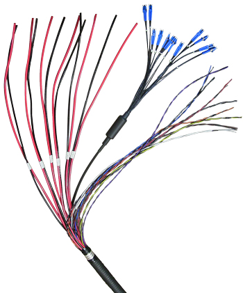
RFS’ HYBRIFLEX Remote Radio Head (RRH) hybrid feeder cabling solution combines optical fiber and DC power for RRHs in a single lightweight aluminum corrugated cable, making it the world’s most innovative solution for RRH deployments. It was developed to reduce installation complexity and costs at Cellular sites.
HYBRIFLEX allows mobile operators deploying an RRH architecture to standardize the RRH installation process. HYBRIFLEX combines optical fiber (multi-mode or single-mode) and power in a single corrugated cable. It may eliminate the need for junction boxes as well as works in conjuction with and can connect multiple RRHs with a single feeder. Standard RFS CELLFLEX® accessories can be used with HYBRIFLEX cable. Both pre-connectorized and on-site options are available.
FEATURES / BENEFITS
- Aluminum corrugated armor with outstanding bending characteristics – Minimizes installation time and enables mechanical protection and shielding
- Same accessories as 1-1/4" coaxial cable
- Outer conductor grounding – Utilizes same grounding methods as coaxial cable
- Lightweight solution and compact design – Decreases tower loading
- Robust cabling – Eliminates need for expensive cable trays and ducts
- Installation of tight bundled fiber optic cable pairs directly to the RRH – Reduces CAPEX and wind load by eliminating need for interconnection
- Optical fiber and power cables housed in single corrugated cable – Saves CAPEX by standardizing RRH cable installation and reducing installation requirements
- UL-Listed, flame-retardant jacket, UV protected assembles - Allows both indoor and outdoor applications
- Maximum robustness – Fully armored cable includes riser trunk and top outdoor breakout

|
Structure
|
| Cable Type |
|
HYBRIFLEX® |
| Fire Performance |
|
Flame Retardant |
| Size |
|
1-1/4" |
|
|
Mechanical Specifications
|
| Outer Diameter Nominal |
mm (in) |
39.4 (1.55) |
| Cable Weight |
kg/m (lb/ft) |
2.5 (1.7) |
| Minimum Bending Radius, Single Bend |
mm (in) |
152 (6) |
| Minimum Bending Radius, Multiple Bends |
mm (in) |
254 (10) |
| Recommended / Maximum Clamp Spacing |
m (ft) |
1 / 1.2 (3.25 / 4) |
|
|
Armor Specifications
|
| Armor Type |
|
Corrugated Aluminum |
| Maximum DC-Resistance of Armor |
Ω/km (Ω/kft) |
0.9 (0.27) |
| Diameter Corrugated Armor |
mm (in) |
35.9 (1.41) |
|
|
Cable Jacket
|
| UV-Protection Individual and External Jacket |
|
Yes |
|
|
DC Power Cable Specifications
|
| Number of DC Pairs |
|
6 |
| Maximum DC-Resistance Power Cable |
Ω/km (Ω/kft) |
1.4 (0.41) |
| Cross Section of Power Cable |
mm² (AWG) |
13.3 (6) |
| DC Cable Single Bending Radius |
mm (in) |
137 (5.4) |
| DC Cable Diameter |
mm (in) |
6.45 (0.254) |
| DC Cable Jacket Material |
|
PVC/Nylon |
| DC Standards (Meets or Exceeds) |
|
For use in UL 83, PVC/Nylon, RoHS/REACH Compliant |
| Break-out Length (Top) |
mm (in) |
812 (32) |
| Break-out Length (Bottom) |
mm (in) |
812 (32) |
| Alarm Wire |
|
18, 18 AWG |
| Alarm Wire Standards (Meets or Exceeds) |
|
UL Standard 1063, 1581 VW-1, MTW Oil and Gasoline RES1 SUNRES (Cable meets UL requirements), RoHS/REACH Compliant |
|
|
F/O Cable Specifications
|
| F/O Cable Type |
|
G657-A1 Single Mode, Bend Tolerant |
| Number of F/O Pairs |
|
12 |
| Core/Clad |
µm |
9/125 |
| Secondary Protection Nominal |
µm (in) |
900 (0.035) |
| Single Bending Radius |
mm (in) |
157 (6.2) |
| Cable Diameter |
|
5.512 (0.217) |
| F/O Standards (Meets or Exceeds) |
|
UL Listed Type OFNR (UL1666), RoHS Compliant |
| Optical Loss |
dB/Km |
0.5 @ 1310 nm
0.5 @ 1550 nm |
| Fiber Termination End 1 |
|
DLC connector |
| Fiber Termination End 2 |
|
DLC connector |
| FO Break-out Length (Top) |
mm (in) |
889 (35) |
| FO Break-out Length (Bottom) |
mm (in) |
889 (35) |
|
|
Testing and Environmental
|
| Storage Temperature |
°C (°F) |
-40 to 70 (-40 to 158) |
| Operation Temperature |
°C (°F) |
-40 to 65 (-40 to 149) |
| Installation Temperature |
°C (°F) |
-20 to 65 (-4 to 149) |
| Jacket Specifications |
|
UL2882, UL Listed |
|
EXTERNAL DOCUMENT LINKS
Installation Guidelines: Download
QuickShip 2.0 Program Information: Download
On-line Factory Test Results: View
NOTES
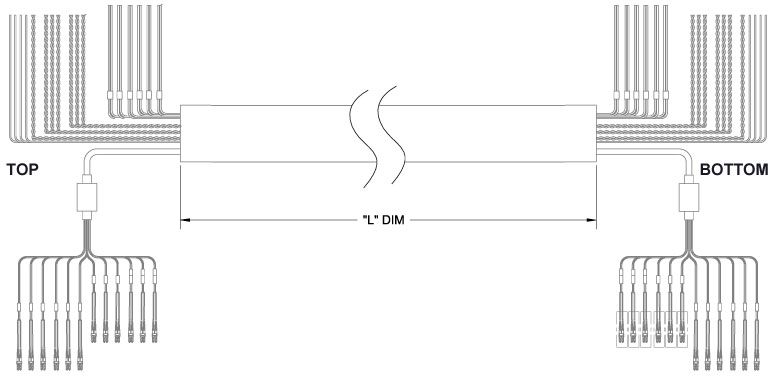
Nominal length equals length of trunk not including top and bottom breakouts; breakout lengths add additionally to the total assembly length tip to tip. Includes 9 pairs of wires used to carry alarm signals.
|
Additional Assembly Lengths
|
| Model Number |
Length (ft) |
| HB114-U6S12-10-TH |
10 |
| HB114-U6S12-20-TH |
20 |
| HB114-U6S12-30-TH |
30 |
| HB114-U6S12-40-TH |
40 |
| HB114-U6S12-50-TH |
50 |
| HB114-U6S12-60-TH |
60 |
| HB114-U6S12-70-TH |
70 |
| HB114-U6S12-80-TH |
80 |
| HB114-U6S12-90-TH |
90 |
| HB114-U6S12-100-TH |
100 |
| HB114-U6S12-110-TH |
110 |
| HB114-U6S12-120-TH |
120 |
| HB114-U6S12-130-TH |
130 |
| HB114-U6S12-140-TH |
140 |
| HB114-U6S12-150-TH |
150 |
| HB114-U6S12-160-TH |
160 |
| HB114-U6S12-170-TH |
170 |
| HB114-U6S12-180-TH |
180 |
| HB114-U6S12-190-TH |
190 |
| HB114-U6S12-200-TH |
200 |
| HB114-U6S12-210-TH |
210 |
| HB114-U6S12-220-TH |
220 |
| HB114-U6S12-230-TH |
230 |
| HB114-U6S12-240-TH |
240 |
| HB114-U6S12-250-TH |
250 |
| HB114-U6S12-260-TH |
260 |
| HB114-U6S12-270-TH |
270 |
| HB114-U6S12-280-TH |
280 |
| HB114-U6S12-290-TH |
290 |
| HB114-U6S12-300-TH |
300 |
| HB114-U6S12-310-TH |
310 |
| HB114-U6S12-320-TH |
320 |
| HB114-U6S12-330-TH |
330 |
| HB114-U6S12-340-TH |
340 |
| HB114-U6S12-350-TH |
350 |
| HB114-U6S12-360-TH |
360 |
|
|
Additional Assembly Lengths
|
| Model Number |
Length (ft) |
| HB114-U6S12-370-TH |
370 |
| HB114-U6S12-380-TH |
380 |
| HB114-U6S12-390-TH |
390 |
| HB114-U6S12-400-TH |
400 |
| HB114-U6S12-410-TH |
410 |
| HB114-U6S12-420-TH |
420 |
| HB114-U6S12-430-TH |
430 |
| HB114-U6S12-440-TH |
440 |
| HB114-U6S12-450-TH |
450 |
| HB114-U6S12-460-TH |
460 |
| HB114-U6S12-470-TH |
470 |
| HB114-U6S12-480-TH |
480 |
| HB114-U6S12-490-TH |
490 |
| HB114-U6S12-500-TH |
500 |
| HB114-U6S12-510-TH |
510 |
| HB114-U6S12-520-TH |
520 |
| HB114-U6S12-530-TH |
530 |
| HB114-U6S12-540-TH |
540 |
| HB114-U6S12-550-TH |
550 |
| HB114-U6S12-560-TH |
560 |
| HB114-U6S12-570-TH |
570 |
| HB114-U6S12-580-TH |
580 |
| HB114-U6S12-590-TH |
590 |
| HB114-U6S12-600-TH |
600 |
| HB114-U6S12-610-TH |
610 |
| HB114-U6S12-620-TH |
620 |
| HB114-U6S12-640-TH |
640 |
| HB114-U6S12-670-TH |
670 |
| HB114-U6S12-700-TH |
700 |
| HB114-U6S12-750-TH |
750 |
| HB114-U6S12-800-TH |
800 |
| HB114-U6S12-850-TH |
850 |
| HB114-U6S12-900-TH |
900 |
| HB114-U6S12-950-TH |
950 |
| HB114-U6S12-1000TH |
1000 |
|
PRE-PACKED HYBRIFLEX KITS FOR EASY INTEGRATION INTO RAYCAP JUNCTION BOXES
RFS now offers Kitting options for most hybrid risers and jumpers that include both the cable assembly and the Raycap inserts. For reference, kits have a “K” as the third digit in the model number. HB158 does not require an additional gland/insert for proper installation and sealing into the Distribution Boxes.
| Kit Model Prefix |
Assembly Prefix |
Assembly Qty |
Raycap Insert Kit |
Insert Kit Contents |
Raycap Insert Kit Qty |
| HBK114 |
HB114 |
1 |
RFS-TRUNK-KIT |
(2) 190‐0620, Insert, M75, 1H, 40mm |
1 |
| HBK058 |
HBF058 |
RFS-JUMP-KIT |
(1) 190‐0621, Insert, M75, 3H, 22mm, Split w/ plugs |
| HBK012 |
HBF012 |
RFS-JUMP-KIT-2 |
(1) 190‐0903, Insert, M75, 2H, 15mm, Split w/ plugs |
| FRK-N |
FR-N |
RFS-FIBER-KIT |
(1) 190‐0657, Insert, M75, 6H, 6.1mm, Split w/ plugs |
|