RLKU158-50CPRH
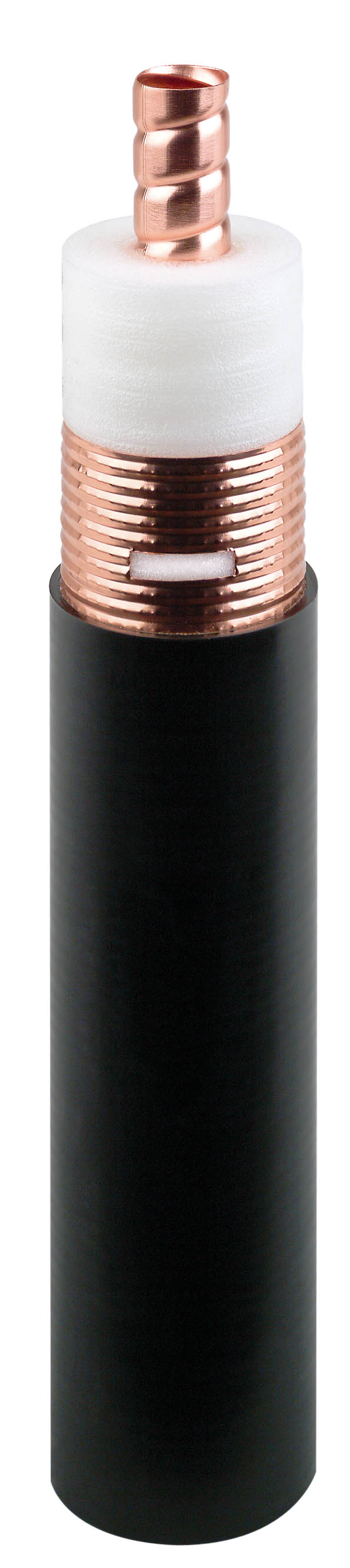
1-5/8" RADIAFLEX® RLKU Cable, A-series
Rev : D | Rev date : 14 May 2024
- RADIAFLEX® functions as a distributed antenna to provide communications in tunnels, mines and large building complexes and is the solution for any application in confined areas.
- Slots in the copper outer conductor allow a controlled portion of the internal RF energy to be radiated into the surrounding environment. Conversely, a signal transmitted near the cable will couple into the slots and be carried along the cable length.
- RADIAFLEX® is used for both one-way and two-way communication systems and because of its broadband capability, a single radiating cable can handle multiple communication systems simultaneously.
- This RADIAFLEX® radiating cable utilize a low-loss cellular polyethylene foam dielectric and a smooth copper outer conductor which offers a superior electrical performance together with good bending properties.
FEATURES / BENEFITS
- Ultra wideband from 30 MHz to 2700 MHz
- For applications in tunnels and buildings
- Low coupling loss variations
- Lowest insertion loss and excellent coupling performance to minimize count of active equipment
- Best-in-class, RF ultra wideband radiating cable, accomodating all current and future commercial radio and private radio service from 30 MHz to 2700 MHz
Technical features
| ||||||
| |||||||||||||||||||||||||||||||||||||||||||||||||||||||||||||||||||||||||||||||||||||||||||||||||||
| |||||||||||||||||||||||||||||||||||||||||||||
| ||||||
| ||||||||||||
| ||||||||||||||||||||||||||||||||||||||||||||||||||||||||||||||||||||||
External Document Links
Notes
- Coupling loss as well as longitudinal attenuation of RADIAFLEX® cables are measured by the free space method according to IEC 61196-4.
- Coupling loss values are measured with a radial (below 540 MHz) or parallel (above 610 MHz) orientated dipole antenna.
- The coupling loss values given in brackets are average values of all three spatial orientations (radial, parallel and orthogonal) of dipole antenna.
- Coupling loss values are given with a tolerance of +5 dB and longitudinal loss values with a tolerance of +5%. Note: Measured values below nominal are better. They are not limited by any tolerance-range.
- In case of a conflict of operational and stop band, please contact RFS for further assistance.
- As with any radiating cable, the performance in building or tunnel environments may deviate from figures based on free space method.
;