RE60-JFN
RADIAFLEX® Elliptical Waveguide, RE-series
Rev : B | Rev date : 12 Oct 2020
- RADIAFLEX® series functions as a distributed antenna to provide communications in tunnels, mines and large building complexes and is the solution for any application in confined areas.
- Slots in the copper outer conductor allow a controlled portion of the internal RF energy to be radiated into the surrounding environment. Conversely, a signal transmitted near the cable will couple into the slots and be carried along the cable length.
- RADIAFLEX® is used for both one-way and two-way communication systems and because of its broadband capability, a single radiating waveguide can handle multiple communication systems simultaneously.
- This RADIAFLEX® radiating waveguide is constructed of longitudinally continuous seam welded, highly conductive copper tube, corrugated and precision formed into an elliptical cross section. It is manufactured in continuous lengths using a special seam welding process developed by the RFS organization. The product offers a superior electrical performance together with good bending properties.
FEATURES / BENEFITS
- Optimized for ultra high frequency applications from 5 GHz to 6 GHz
- Best-in-class, RF wideband radiating waveguide with technology agnostic performance
- Designed for a variety of in-tunnel applications
- Lowest insertion loss and excellent coupling performance to minimize count of active equipment; low coupling loss variations
- Maintains functionality even in case of a fire
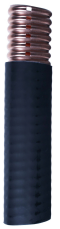
RE elliptical waveguide
General Specifications |
|---|
| Size | | RE60 |
|
Electrical Specifications |
|---|
| Max. Operating Frequency | MHz | 6000 | | Cable Type | | RE | | Frequency Selection | MHz | 6000 |
|
Mechanical Specifications |
|---|
| Jacket Description | | Halogen free, non corrosive, flame and fire retardant, low smoke, polyolefin | | Slot Design | | Milled | | Outer Conductor Material | | Corrugated Copper Tube | | Dimension over Jacket | mm (in) | 56 x 33 (2.2 x 1.3) | | Min. Bending Radius E Plane w/o rebending | mm (in) | 200 (8) | | Min. Bending Radius H Plane w/o rebending | mm (in) | 550 (22) | | Min. Bending Radius E Plane with rebending | mm (in) | 300 (12) | | Min. Bending Radius H Plane with rebending | mm (in) | 800 (31) | | Cable Weight | kg/m (lb/ft) | 1.1 (0.74) | | Indication of Slot Alignment | | Printing on jacket | | Recommended / Maximum Clamp Spacing | m (ft) | 2 (5) | | Minimum Distance to Wall | mm (in) | 50 (2) |
|
Testing and Environmental |
|---|
| Jacket Testing Methods | | Test methods for fire behaviour of cable :
IEC 60754-1/-2 smoke emission: halogen free, non corrosive
IEC 61034 low smoke
IEC 60332-1 flame retardant
IEC 60332-3-24 fire retardant |
|
Temperature Specifications |
|---|
| Storage Temperature | °C(°F) | -70 to 85 (-94 to 185 ) | | Installation Temperature | °C(°F) | -25 to 60 (-13 to 140 ) | | Operation Temperature | °C(°F) | -40 to 85 (-40 to 185 ) |
|
Attenuation and Power Rating |
|---|
| Frequency, MHz | Longitudinal Loss, dB/100 m (dB/100 ft) | Coupling Loss 50%, dB | Coupling Loss 95%, dB |
| 5000 |
4.90 (1.49) |
74 |
80 |
| 5100 |
4.90 (1.49) |
74 |
80 |
| 5200 |
4.80 (1.46) |
74 |
80 |
| 5300 |
4.80 (1.46) |
74 |
80 |
| 5400 |
4.80 (1.46) |
74 |
80 |
| 5500 |
4.80 (1.46) |
74 |
80 |
| 5600 |
4.80 (1.46) |
74 |
80 |
| 5700 |
4.80 (1.46) |
74 |
80 |
| 5800 |
4.80 (1.46) |
74 |
80 |
| 5900 |
4.80 (1.46) |
74 |
80 |
| 6000 |
4.80 (1.46) |
74 |
80 |
|
Notes
- Coupling loss as well as longitudinal attenuation of RADIAFLEX® elliptical waveguides is measured by the free space method according to IEC 61196-4.
- Coupling loss values are measured with a log-periodic antenna with gain of approx. 6 dBi in specified frequency range.
- The coupling loss values are average values of the three spatial orientations (radial, parallel and orthogonal) of log-periodic antenna.
- Coupling loss values are given with a tolerance of ±6 dB and longitudinal loss values with a tolerance of ±5%.
- As with any radiating element, the performance in building or tunnel enviorments may deviate from figures based on free space mthod.