E150J
FLEXWELL® Standard Elliptical Waveguide
Rev : D | Rev date : 29 Oct 2020
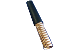
FLEXWELL® elliptical waveguide is constructed of longitudinally continuous seam welded, highly conductive copper tube, corrugated and precision formed into an elliptical cross section. It is manufactured in continuous lengths using a special seam welding process developed by the RFS organization.
The corrugation design achieves high transverse stability, flexibility and crush strength for superior handling and forming at an installation. The inherent strength and flexibility of FLEXWELL® waveguide allows on location, a continuous length of waveguide to be run directly from a tower-mounted antenna to the equipment building.
A FLEXWELL® elliptical waveguide feeder requires less planning and reduces installation costs when compared to a feeder system using a rigid rectangular waveguide.
FLEXWELL® waveguide is available cut to length with factory attached connectors or in continuous lengths for termination in the field.
FLEXWELL® waveguide is available cut to length with factory attached connectors or in continuous lengths for termination in the field.
FEATURES / BENEFITS
- Designed for optimum system performance
- Excellent electrical performance
- Low loss and low VSWR (low return loss)
- Electrical test made on every waveguide during manufacturing
- Every waveguide undergoes 24 hour pressure test
- Reduced installation cost compared to rigid rectangular waveguides due to flexibility
- No need of flange joints, twist section and bends
- Easy transportation in coils or on drums
- Cutting at exact length and connectorizing in the field
Technical features
| |||||||||
| ||||||||||||
| |||||||||||||||||||||||||||||||||
| ||||||||||||
| |||||||||||||||||||||||||||||||||||||||||||||||||||||||||||||||||||||||||||||||||||||||||||||||||||||||||||||||||||||||||||||||||||||||||||||||||||||||||||||||
External Document Links
Notes
VSWR values include connectors and are valid for frequency band of connectors.
Max. Operating Band: 10.80 - 15.35 GHz